I have been using FreePCB to layout the boards I design. It is getting a little old and no longer has all the capabilities I desire. But it has all the pads I have designed over the years for hand building of SMT boards. I needed a pad for a component ( USB C connector with through hole pins) that requires slots for correct assembly. I have figured out a relatively easy way to design and produce such pads.
Making A Simple Plated Through Linear Slotted Pad in FreePCB.
You will use 2 surface mount pads on the top and bottom layers. And two through hole drilled pads. Call them holes one and two. I will assume you know or can figure out how to place the pads in relation to each other. Either manually or by using the set function included on each pad.
To get a proper CAM file you will have to connect all the pads together. First do this on a schematic that has all the pins connected, surface mount and through hole. That gives you a good net list.
After you lay down the component with slots in FreePCB and complete the wiring, on the top layer connect the surface mount pad to hole one. And then connect it to hole two. Lay down the "wires (traces)" as you do each connection.
Do the same for the bottom surface mount pad. Finally connect the two drilled pads together. I do that on the top and bottom layers. It may only be necessary on one layer. I haven't checked.
When editing the CAM drill file, the file you start with will look something like this. This file has eight holes for four slots ==>
.....
T02
X015624Y007852
X016215Y007852
X015624Y004447
X016215Y004447
X017093Y007852
X017408Y007852
X017093Y004447
X017408Y004447
T03
.....
The file with working slots will look like this ==>
.....
T02
X015624Y007852G85X016215Y007852
X015624Y004447G85X016215Y004447
X017093Y007852G85X017408Y007852
X017093Y004447G85X017408Y004447
T03
.....
Connecting the pads together with traces as suggested above eliminates DRC errors. Do a ratline recalculation before doing a Design Rule Check.
I have checked this on Gerbv and another rendering program. They both show correct slots. As does OSH Park in their rendering of the completed board.
There is an online discussion about this method of making slots in FreePCB. You can find it here.
Space-Time Productions is a participant in the Amazon Services LLC Associates Program. We earn advertising fees when you use this link Amazon.com and other Amazon links we provide.
Engineering is the art of making what you want from what you can get at a profit.
Wednesday, November 9, 2022
Tuesday, September 6, 2022
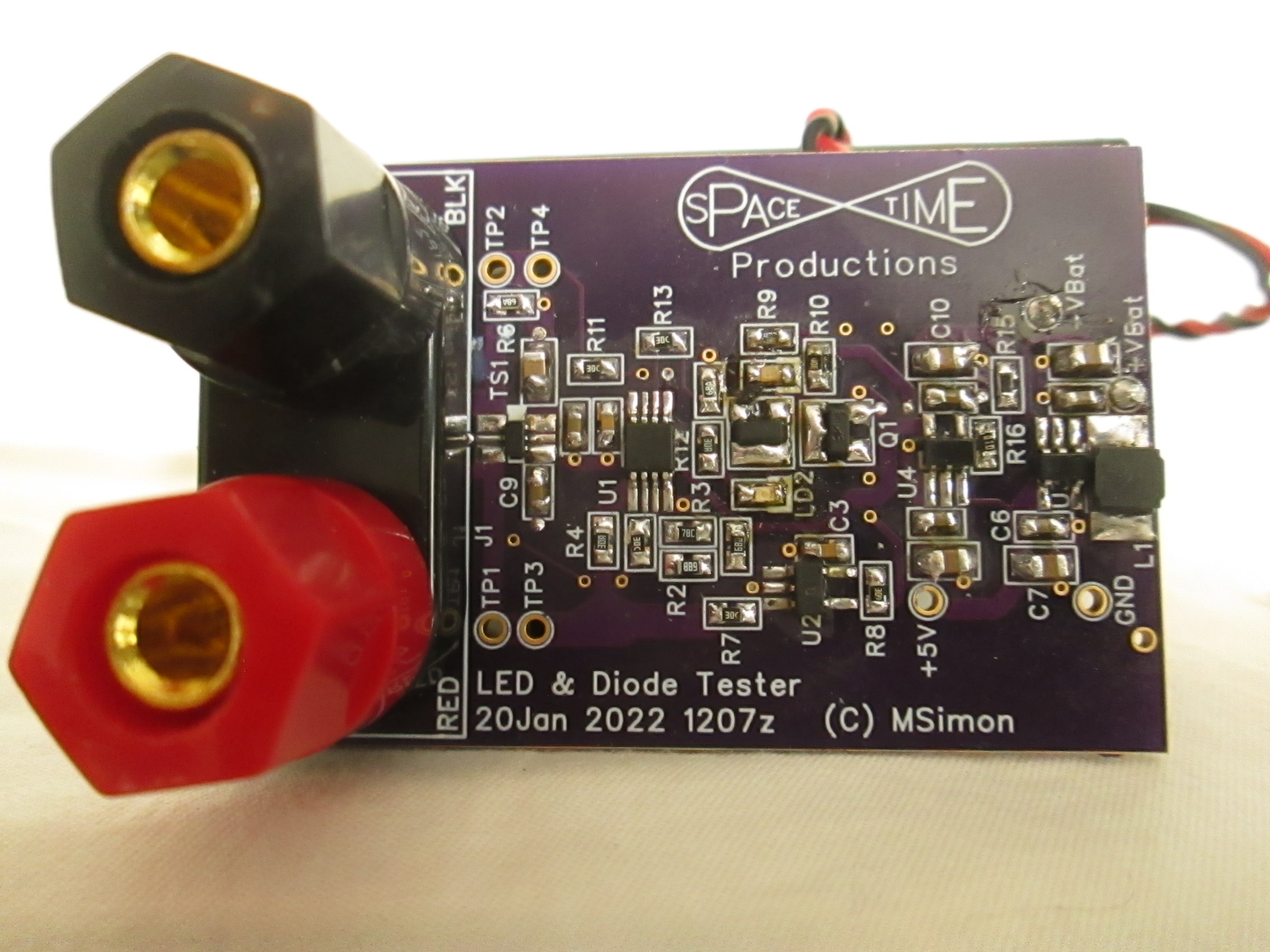
Surface Mount LED and Diode Tester
If you build a lot of prototype boards as I do, you know the problems of getting surface mount LEDs and diodes oriented properly for mounting. Even if you only build a few the frustrations are evident. The markings (if any) are nearly invisible. And the parts are smaller than pebbles. So I decided to solve the problem. Finally. I designed a battery operated (two AA cells) tester that puts out 4.5 volts maximum so LEDs are not ovrervoltaged in the reverse direction during testing. It also current limits so no more than 1 mA flows through the probes under any condition. That allows you to compare LED brightness. In the reverse direction no LEDs in the unit light up. If the probe tips are shorted a Red LED Lights. If the probe tips are aligned with the forward direction of the diode or LED a green LED lights up and a current of 1 mA through the probes will show the LED color if you are testing one.
A current mirror makes the current through the green LED the same as the current through the probes. So you get a crude visual ohm meter. All in all much handier than trying to make an ohm meter do the job. Or trying to use a power supply and a resistor. The minimum voltage across the diode at 1mA current that works with the tester is about 50mV. This voltage makes the tester functional with diodes that can handle higher currents. Higher current diodes also tend to be larger and better marked.
For the project I got the binding posts from Amazon. I also built a neat little Meter Probe Jack Adapter using these banana pins and these meter safety banana connector sockets. The banana jacks/sockets that accept meter safety banana plugs are currently out of stock. I have found no other source of supply I'd even consider dealing with. The reason for the adapter was to use this surface mount test probe without having to modify the connectors. The test probe tips need to be cleaned thouroughly to be conductive. It seems like plating would help here. I'm going to try this silver plating solution from Amazon.
You will notice I have included offset current balancing resistors to reduce the offset voltages if you use an op-amp different from the LMR342.The comparator input bias currents are so low they can be ignored in this application. The input resistor is just for protection.
The board pictured is an earlier version. I have designed a board ( 2 Sep 2022 ) that uses fewer parts. When that board arrives I will test it and announce the results. The Schematic for that board is included in the downloads. I replaced a voltage regulator and associated capacitors with a diode. A MOSFET was replaced with the output of a comparator. An output resistor was eliminated.
The schematic, parts list and parts layout are available for download here. Boards are available for $16.50 for two plus $5.50 shipping in the USA. Use the Paypal link and ask for "LED and Diode Tester 20Jan 2022 1207z". Delivery can take up to four weeks depending on availability and the USPS. You can also order the parts list directly from Mouser using this link. You can edit what you buy. I like extras because losing parts is not unusual.
The board looks like this: Powered down.
 Red LED.
 Green LED.
 The Adapter board and Surface Mount Test Probe. The red and black safety connecters are no longer available. The Gold Plated Banana plugs still are.
Update: 7 Sept 2022 0135z
It turns out the safety connectors are again available from Amazon. Which may mean you would like the "Dual Adapter 13Feb2022 0857z" board for $6.45 for two plus $5.50 shipping.
Space-Time Productions is a participant in the Amazon Services LLC Associates Program. We earn advertising fees by advertising and linking to Amazon.com.
Engineering is the art of making what you want from what you can get at a profit.
A current mirror makes the current through the green LED the same as the current through the probes. So you get a crude visual ohm meter. All in all much handier than trying to make an ohm meter do the job. Or trying to use a power supply and a resistor. The minimum voltage across the diode at 1mA current that works with the tester is about 50mV. This voltage makes the tester functional with diodes that can handle higher currents. Higher current diodes also tend to be larger and better marked.
For the project I got the binding posts from Amazon. I also built a neat little Meter Probe Jack Adapter using these banana pins and these meter safety banana connector sockets. The banana jacks/sockets that accept meter safety banana plugs are currently out of stock. I have found no other source of supply I'd even consider dealing with. The reason for the adapter was to use this surface mount test probe without having to modify the connectors. The test probe tips need to be cleaned thouroughly to be conductive. It seems like plating would help here. I'm going to try this silver plating solution from Amazon.
You will notice I have included offset current balancing resistors to reduce the offset voltages if you use an op-amp different from the LMR342.The comparator input bias currents are so low they can be ignored in this application. The input resistor is just for protection.
The board pictured is an earlier version. I have designed a board ( 2 Sep 2022 ) that uses fewer parts. When that board arrives I will test it and announce the results. The Schematic for that board is included in the downloads. I replaced a voltage regulator and associated capacitors with a diode. A MOSFET was replaced with the output of a comparator. An output resistor was eliminated.
The schematic, parts list and parts layout are available for download here. Boards are available for $16.50 for two plus $5.50 shipping in the USA. Use the Paypal link and ask for "LED and Diode Tester 20Jan 2022 1207z". Delivery can take up to four weeks depending on availability and the USPS. You can also order the parts list directly from Mouser using this link. You can edit what you buy. I like extras because losing parts is not unusual.
The board looks like this:


Update: 7 Sept 2022 0135z
It turns out the safety connectors are again available from Amazon. Which may mean you would like the "Dual Adapter 13Feb2022 0857z" board for $6.45 for two plus $5.50 shipping.
Space-Time Productions is a participant in the Amazon Services LLC Associates Program. We earn advertising fees by advertising and linking to Amazon.com.
Engineering is the art of making what you want from what you can get at a profit.
Monday, February 21, 2022
Nostalgia Strikes Deep
I was looking around the net for this January 1975 Popular Electronics Magazine cover. The start of the Computer Revolution. I knew it the minute I saw it and rushed to tell my girlfriend (in 1975).
 You can read more about it at Vintage Computer.net.
I had a hand in all that. I designed the S-100 I/O board that went into the worldd's first BBS. A precursor of the internet. I was also writing Magazine articles. My first published article was in the March 1978 issue of Kilobaud. "Faster Erase Times" It was about building your own high intensity ultraviolet light to erase EPROMs. I sold kits of the hard to get parts. I sold 500. Back then you had to build your own. Buying was way too expensive.
I also wrote something for Dr. Dobb's "Building a Programable Frequency Synthisizer". It was about Phase Locked Loops. I still use the CD4046 and variants.
Which brings me to the present. I just bought a 3D printer (I'm in the process of assembly - I'm going slow and methodical) and thus have joined in with the next revolution. I plan to write articles.
My wife and I (the same girlfriend from January '75) made "Support the Revolution - Buy a Computer" t-shirts back in the day. And now ==> "Support the Revolution - Buy a 3D Printer".
==================
This is the printer I'd buy if I was starting out today. I got the previous model with a silent motherboard upgrade.
This is the best Ender 3 assembly video I have been able to find. It is actually a series of 5 videos. The link is to the first.
Space-Time Productions is a participant in the Amazon Services LLC Associates Program. We earn advertising fees by advertising and linking to Amazon.com.
Engineering is the art and science of making what you want from what you can get at a profit.
Subscribe to:
Posts (Atom)


